|
Ever wondered why a dealership repair hits your pocket harder than an independent shop? Let's chat about OEM and aftermarket parts in the auto world and find the sweet spot between quality and savings.
The Inside Scoop on Cost and Quality Dealerships boast about OEM parts' premium quality, but aftermarket parts often bring budget-friendly options to the table. So, are you getting a bang for your buck? Let's find out! Quality Surprises in Aftermarket Parts Surprise, surprise! Not all aftermarket parts are created equal. Some roll off the same assembly line as their OEM counterparts, minus the fancy logo. It's like a secret handshake among car parts! Pros and Cons: Aftermarket Edition Let's be real; aftermarket parts aren't just about price. They offer variety, availability, and potentially high quality. Need a part pronto? Aftermarket's got your back, and you won't be stuck in repair limbo for weeks. Aftermarket Affordability: Myth or Reality? Yes, aftermarket parts are often cheaper, but don't dismiss them as the underdogs. Sometimes, they flex quality that rivals OEM. It's like finding a hidden gem at your local auto store! OEM Charm: Quality Assurance Straight from the Dealer If you're all about peace of mind and a straightforward shopping experience, OEM parts are your go-to. No guessing games; just head to the dealership, ask for the part, and you're set! OEM Goodies: Warranty Wonderland Did you know OEM parts come with a top-notch warranty? Plus, if your car is still under warranty, using OEM parts might be non-negotiable. It's like an insurance policy for your car's health! Picking Your Winning Team: OEM or Aftermarket? Let's wrap it up with a bow. Newer car with a warranty? OEM is your MVP. Need a quick fix and love choices? Aftermarket might be your speed. It's all about your car's needs, your timeline, and your budget. Insurance Insights: OEM vs. Aftermarket Dilemma Does your insurance prefer OEM for factory precision, or are they on team aftermarket for cost savings? It's a puzzle, and your policy holds the key. Read the fine print! Clearing the Fog Around Car Parts Still got burning questions? We've got you covered. From part quality to insurance quirks, we're debunking myths and ensuring your car stays roadworthy without breaking the bank. The Verdict: Car Value Unmasked Worried about your car's resale value? In most cases, choosing OEM or aftermarket won't make a dent. Unless your buyer has a magnifying glass, your ride is still a star on the resale stage! Gear up for a smoother ride in the world of car repairs. Let's make your car purr without emptying your wallet. Your Google search ends here – the road to automotive wisdom starts now
0 Comments
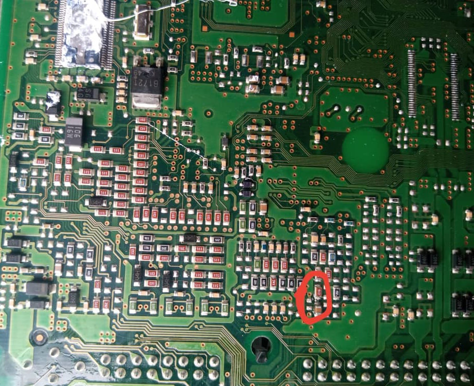
In the fast-evolving landscape of automotive technology, understanding Electronic Control Units (ECUs) is paramount for both enthusiasts and professionals alike. As vehicles become more reliant on sophisticated electronic systems, the ability to diagnose and repair ECU hardware faults is a skill that sets automotive experts apart. Enter Electronic Repair Egypt's ECU Hardware Repair Course, your definitive solution to mastering ECU diagnostics and restoration.
Why ECU Hardware Repair Matters The ECU serves as the brain of modern vehicles, controlling crucial functions such as engine performance, fuel efficiency, and emissions. When an ECU malfunctions, it can lead to a cascade of issues, from erratic engine behavior to diminished fuel economy. Traditional repair methods often involve costly replacements or outsourcing to specialized services, resulting in downtime and inflated expenses. The Electronic Repair Egypt Advantage Electronic Repair Egypt bridges this gap with its cutting-edge ECU Hardware Repair Course. Developed by industry experts with years of hands-on experience, this course is designed to empower automotive enthusiasts, technicians, and professionals with the knowledge and skills needed to diagnose and repair ECU hardware faults effectively. What You'll Learn
Why Choose Electronic Repair Egypt?
Unlock Your Automotive Potential Whether you're a seasoned professional looking to expand your skill set or an automotive enthusiast eager to delve into the world of ECU diagnostics, Electronic Repair Egypt's ECU Hardware Repair Course is your gateway to success. Join us today and unlock a world of automotive possibilities. Enroll Now Visit Electronic Repair Egypt's ECU Hardware Repair Course to enroll and take the first step towards mastering ECU hardware repair. electricity - the invisible force that powers our lives. But did you know that there are two types of electricity? That's right, there's AC and DC, and they're as different as night and day - well, technically as different as alternating current and direct current, but you get the point. Let's start with AC, or alternating current. As the name suggests, AC switches direction regularly, like a pendulum. This is the type of electricity that powers our homes, businesses, and pretty much everything else that needs a steady stream of power. Think of it like a conveyor belt that's constantly moving, carrying electricity from one place to another. Now, DC, or direct current, is a bit more straightforward. It flows in one direction, like a river. DC is used for things like batteries, and it's what powers your car and your phone. Think of it like a straw - the electricity flows in one direction, like the liquid you're sipping through the straw. But what's the real difference between AC and DC? Well, for one thing, AC can be a bit more shocking - literally. If you've ever accidentally touched a live wire, chances are it was carrying AC. That's because AC is more likely to cause muscle contractions, which is why it's more dangerous. On the other hand, DC is more predictable. It's like a faithful old dog that always does what you want it to do. DC is also more efficient than AC, which is why it's used for things like electric cars. So there you have it - the differences between AC and DC. Of course, this is all just scratching the surface, and there's a lot more to know about electricity. But hey, at least now you can impress your friends at parties with your newfound knowledge. Just don't go sticking your fingers in any outlets, okay? Electricity is an integral part of our lives, and it powers almost everything we use. Understanding how electricity works can help us appreciate the convenience it provides and even make us more energy-efficient. In this article, we'll take a closer look at electricity and how it works.
At its most basic level, electricity is the movement of electrons between atoms. Electrons are negatively charged particles that surround the nucleus of an atom. When these negatively charged particles move from one atom to another, an electric current is created. This flow of electrons is what we call electricity. Electricity can be generated in a variety of ways, but most commonly, it is produced by using generators that convert mechanical energy into electrical energy. This is achieved by using a conductor to move a magnetic field around a coil of wire. The movement of the magnetic field induces an electrical current in the wire, which generates electricity. Electricity can also be generated through chemical reactions, such as in batteries, or by using solar cells that convert sunlight into electrical energy. Once electricity is generated, it can be transmitted over long distances using power lines. The voltage of the electricity is increased using transformers, which makes it easier to transmit over long distances. Electricity can be dangerous if not handled properly. Electric shock occurs when the body comes into contact with an electric current. The severity of the shock depends on the amount of current flowing through the body, the length of time the current flows, and the path the current takes through the body. To prevent electric shock, it's important to always follow safety guidelines when working with electricity. This includes wearing protective gear, such as gloves and safety glasses, and making sure that electrical equipment is properly grounded. Never touch electrical equipment if your hands are wet, and always unplug equipment before performing any maintenance or repairs. Electronic boards are the backbone of modern technology, and their reliability is essential for the safe and effective operation of countless devices. However, as electronic components become smaller and more complex, testing these boards has become increasingly challenging. Traditional testing methods can only identify certain types of defects, leaving many potential issues undetected. That's where thermal cameras come in - a game-changer in the field of electronic board testing.
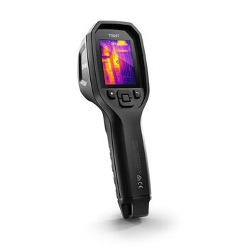
What is a Thermal Camera? A thermal camera is a type of camera that detects infrared radiation and converts it into an image visible to the human eye. The camera detects the heat emitted by an object and represents it as a color gradient, with hotter areas appearing as bright colors, and cooler areas appearing as darker colors. Thermal cameras are widely used in a variety of industries, from building inspections to law enforcement. How are Thermal Cameras Used in Electronic Board Testing? Thermal cameras are particularly useful in the testing of electronic boards because they can identify defects that are not visible to the naked eye. The thermal imaging process is non-contact and non-destructive, allowing for quick and accurate detection of defects without damaging the board or its components. Thermal cameras can detect a wide range of defects, including:
What are the Benefits of Using Thermal Cameras in Electronic Board Testing? The benefits of using thermal cameras in electronic board testing are numerous:
Thermal cameras have revolutionized the way electronic boards are tested, providing a quick, accurate, and non-destructive solution for identifying defects. As the complexity of electronic boards continues to increase, thermal cameras will become an essential tool for quality control and ensuring the reliability of modern technology. By investing in thermal imaging technology, manufacturers can improve the quality of their products and maintain their competitive edge in the marketplace. |
Auto Tuning Blog “The content provided is for educational and informational purposes only.”
Categories
All
|
Please note that we don't accept Orders / support requests sent direct to our email address.
Electronic Repair Company |
|
|
All Rights Reserved, ©2024 Electronic Repair Company


